Cooling Technology
Air cooling alone can no longer remove the heat generated by modern AI infrastructure
The Liquid Cooling Stack: Moving heat from the servers to the outside environment
Compute Hardware →
CPUs, GPUs, memory
Server Cooling →
DLC, IMM, RDHx
Rack Cooling →
CDU, Pump, Manifold, etc.
Facility Loop →
Warm water piping, pumps
Heat Rejection →
Dry Coolers, Adiabatic, Chillers
(Technology abbreviations: DLC - Direct to Chip cooling, IMM - Immersive Cooling, RDHx - Rear Door Heat Exchanger, CDU - Coolant Distribution Unit)
The Limits of Air Cooling
Rising processor power and increasing rack densities are forcing data centers to rethink how heat is removed from modern systems.
The era of traditional air-cooled data center infrastructure is rapidly coming to an end. While air cooling has served the industry well for decades, the rapid rise in system power driven by AI workloads is pushing data center thermal design beyond what air alone can realistically support.
TDPs for performance-oriented server CPUs now typically fall in the 300–400 watt range, with the highest-end SKUs approaching 500 watts. Modern DDR5 server memory is also power hungry, with high-capacity RDIMMs consuming roughly 12–18 watts per DIMM. When networking, storage, and other supporting components are included, a dual-socket server can easily approach 1.5 kW before any accelerators are added.
Add AI accelerators to the equation and the numbers increase dramatically. Today's leading GPUs commonly operate in the 700-watt range, with next-generation accelerators already approaching or exceeding 1000 watts per device.
To illustrate how this affects rack-level power density, consider a reasonable transitional AI rack configuration. A typical 42U rack populated with 21 2U servers might include roughly one-third GPU-equipped nodes, each containing four GPUs, with the remaining servers configured as CPU-only nodes.
Under those assumptions:
-
A CPU-only server may consume roughly 900–1,050 watts depending on configuration.
-
A GPU-equipped server with four accelerators may consume roughly 3,700–3,800 watts.
When these systems are combined in a single rack, the total power consumption quickly climbs into the range of roughly 38–42 kW per rack.
This is already far beyond the design envelope of many traditional enterprise data centers, where racks historically averaged 5–10 kW, with 15–18 kW considered relatively dense only a few years ago.
And this example is not an extreme frontier-AI configuration. It represents a plausible, near-term infrastructure step for organizations moving beyond experimentation and into serious AI-capable computing environments.
As rack power densities climb, the amount of heat that must be removed from the data center increases proportionally. At these levels, relying on air cooling alone becomes increasingly difficult, inefficient, and in some cases simply impractical. As a result, many organizations are beginning to explore liquid cooling technologies as a more efficient way to remove heat directly from the components generating it.
This is why you won't be able to exclusively rely on air cooling anymore. You will have to move to liquid cooling in some form or other. Alternatively, you could outsource a bunch of your IT to a third party or a cloud, but there are very significant cost, flexibility, and other concerns that need to be rigorously examined. That said, let's take a look at liquid cooling technology, how it works in general, and then lay out technology choices.
How Liquid Cooling Works
As data center power densities continue to climb, removing heat efficiently becomes one of the central engineering challenges in modern infrastructure design. Traditional air cooling can still play a role in some environments, but it becomes increasingly difficult to move large amounts of heat using air alone.
Liquid cooling offers a far more efficient way to capture and transport heat away from system components. Water can carry roughly 3,000 to 4,000 times more heat per unit volume than air, allowing heat to be removed directly from CPUs, GPUs, and other high-power devices and transported out of the rack and ultimately out of the facility.
To understand the scale of the problem, consider the airflow required to remove heat using air cooling alone. Removing roughly 40 kW of heat from a single rack would require on the order of 6,000–7,000 cubic feet per minute (CFM) of airflow. That level of airflow is difficult to deliver consistently within a typical data center environment and can create additional challenges around airflow management, fan power consumption, and acoustic noise.
Liquid cooling approaches the problem differently. Rather than attempting to cool the entire volume of air surrounding a rack, liquid cooling removes heat directly from the small areas of silicon where it is generated and transports that heat away through a closed-loop liquid system.
At a high level, most liquid cooling systems follow a relatively simple heat-removal loop. The diagram below illustrates the major components involved and how heat moves from the servers to the outside environment.
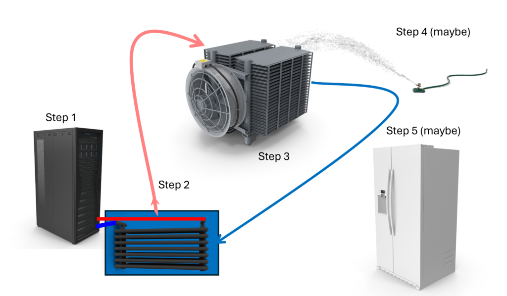
Step 1 — Server Cooling Loop
Pumps circulate liquid through each node in the rack in a closed loop. As the liquid flows through the system, it absorbs heat generated by processors, memory, and other components and carries that heat out of the rack.
Several different approaches are used today to capture heat from the servers themselves. The three most common approaches are direct-to-chip cooling, rear door heat exchangers, and immersion cooling.
Direct-to-chip cooling
Direct-to-chip cooling removes heat from processors and other high-power components using cold plates attached directly to the devices. Liquid flows through these cold plates, capturing heat from the silicon and carrying it away through the cooling loop. This approach is currently one of the most widely deployed liquid cooling technologies for high-performance computing and AI systems.
Rear door heat exchangers
Rear door heat exchangers capture heat from servers using a liquid-cooled radiator mounted on the back of the rack. As hot air exits the rack, it passes through the heat exchanger where heat is transferred to the liquid cooling loop. This approach allows many existing air-cooled systems to operate at higher power densities without requiring major changes to server hardware.
Immersion cooling
Immersion cooling submerges servers directly into a bath of dielectric fluid. Heat from the components is transferred directly into the surrounding liquid and carried away through a heat exchanger. Immersion systems can remove large amounts of heat efficiently and can support extremely high rack power densities.
Regardless of which approach is used to capture heat from the servers, the next step is to transfer that heat out of the rack and into the facility cooling infrastructure.
Single-Phase vs Two-Phase Cooling
Liquid cooling systems can also be categorized as single-phase or two-phase systems.
In single-phase cooling, the liquid coolant remains in a liquid state as it circulates through the cooling loop, absorbing heat from the components and carrying it away through the cooling system.
In two-phase cooling, the coolant changes phase during the process. As heat is absorbed, the liquid boils and becomes vapor, carrying heat away very efficiently. The vapor is then condensed back into liquid form and recirculated.
Both approaches are used in modern data center cooling systems. Single-phase systems are currently more common but two-phase can offer advantages in some situations. This is a rapidly evolving area that bears watching.
Step 2 — Coolant Distribution Unit (CDU)
Now that heat has been captured by the liquid circulating through the servers, it must be transferred out of the rack and into the facility cooling infrastructure.
This function is performed by a Coolant Distribution Unit (CDU).
A CDU acts as the interface between the server liquid loop and the facility water loop. Inside the CDU, a liquid-to-liquid heat exchanger transfers heat from the server cooling circuit to the building’s water system. The warmed facility water is then pumped out of the data center to be cooled.
CDUs also perform several important operational functions within the cooling system.
• regulate coolant flow through the server loop
• monitor temperature and pressure within the cooling circuit
• isolate the server cooling loop from the facility water system
CDUs come in a variety of sizes and configurations. Some are deployed at the rack level, while larger units may support multiple racks or entire rows of racks.
Step 3 — Heat Rejection (Dry Coolers)
Once heat has been transferred to the facility water loop, the next step is to remove that heat from the building.
In many liquid-cooled data centers, this is accomplished using dry coolers located outside the facility, typically on the roof or adjacent to the building.
Dry coolers function much like large radiators. Warm water from the facility loop flows through coils inside the unit while large fans pull outside air across the radiator surface. As the air passes across the coils, heat is transferred from the water to the air and released into the atmosphere.
An important advantage of liquid cooling is that the facility water does not need to be especially cold. In many systems, inlet water temperatures of around 80°F (27°C) are entirely acceptable, and industry guidance from organizations such as **ASHRAE indicates that temperatures in the 85–89°F range can often be supported depending on the system design.
Because the cooling system can operate with relatively warm water, it becomes possible to reject heat using outside air alone during much of the year in many climates.
This is where dry coolers become particularly effective. Unlike traditional chillers, which rely on energy-intensive mechanical refrigeration, dry coolers simply transfer heat from water to air. As a result, dry coolers consume significantly less electrical power than chiller-based cooling systems.
For many facilities, this means that a large portion of the cooling load can be handled without using chillers at all. In favorable climates, dry coolers may provide sufficient cooling capacity for most of the year.
However, during periods of very high outdoor temperatures, additional cooling assistance may be required. This leads to the next stage in the system.
Step 4 — Adiabatic Assist
During periods of higher outdoor temperatures, many facilities use adiabatic cooling to extend the operating range of dry coolers.
Adiabatic cooling works by pre-cooling the air before it passes through the dry cooler radiator. In these systems, water is sprayed onto a porous medium or evaporative surface located in front of the radiator. As air flows through this material, a portion of the water evaporates, lowering the air temperature before it reaches the heat exchanger coils.
This evaporative process allows the radiator to remove more heat from the facility water loop than it could using outside air alone.
Because adiabatic systems operate only when needed, they can significantly extend the number of hours per year that dry coolers can reject heat without requiring mechanical refrigeration. In many climates, this approach allows data centers to operate without chillers for the majority of the year.
While adiabatic systems do require a small amount of water and additional control hardware, they are still far simpler and more energy efficient than traditional chiller-based cooling systems.
However, under extreme environmental conditions or when very low cooling water temperatures are required, mechanical chillers may still be necessary. This leads to the final stage of the cooling system.
Step 5 — Chillers
Under certain conditions, chillers may still be required to support the cooling system.
Chillers use refrigeration to remove heat from the facility water loop and lower the water temperature before it is returned to the data center. Unlike dry coolers or adiabatic systems, chillers rely on compressors and refrigeration cycles to move heat, making them significantly more complex and energy intensive.
In many modern liquid-cooled facilities, chillers are no longer the primary cooling mechanism. Instead, they serve as a supplemental or backup system used during periods of extremely high outdoor temperatures or when unusually low cooling water temperatures are required.
Because liquid-cooled infrastructure can operate with relatively warm water temperatures, dry coolers and adiabatic systems are often able to handle the majority of the facility’s cooling load. As a result, chillers may operate only during the hottest periods of the year or under special operating conditions.
This approach allows facilities to significantly reduce their reliance on refrigeration while still maintaining the ability to support demanding computing workloads.
The Total Cost of Ownership Equation
One of the common assumptions about liquid cooling is that it is inherently more expensive than traditional air cooling. In reality, the economics can often favor liquid cooling once system power consumption reaches higher levels.
Air cooling requires the entire volume of a data center to be cooled so that chilled air can be delivered to the servers. Large computer room air conditioning (CRAC) units or air handlers must cool the air, circulate it through the data center, and maintain appropriate temperatures throughout the facility.
Liquid cooling approaches the problem very differently. Instead of cooling the entire room, liquid cooling removes heat directly from the components generating it — CPUs, GPUs, memory, and other high-power devices — and transports that heat out of the building through a much more efficient medium.
Because liquid cooling captures heat directly at the source, 80–95% of the heat generated by the servers can be removed through the liquid cooling loop before it ever enters the room air. This dramatically reduces the cooling load placed on traditional air conditioning systems.
In many liquid-cooled facilities, the data center air conditioning system no longer needs to remove the full heat output of the computing equipment. Instead, it primarily supports environmental control for personnel and other secondary loads. This change can significantly reduce the size, power consumption, and operating costs of the air conditioning infrastructure within the data center.
Liquid cooling can also improve overall data center energy efficiency. Because most of the heat is removed directly through the liquid cooling loop, facilities can dramatically reduce the amount of energy required for air handling and mechanical refrigeration. In many deployments this results in significantly lower Power Usage Effectiveness (PUE) values compared with traditional air-cooled environments.
At rack power levels approaching 40 kW and beyond, liquid cooling rapidly becomes the more practical and efficient approach to removing heat from modern computing systems.
With rising rack power consumption, increasing energy costs, and the growing demand for more powerful computing systems, liquid cooling may ultimately become less a question of “if” and more a question of “when.”
Cooling Technology Vendors
As you can see from the table below, the liquid-cooling ecosystem includes a wide range of companies providing different parts of the cooling stack, from server-level cooling technologies to rack infrastructure and facility heat-rejection systems.
Cooling Stack Category | Description |
Server-Level Cooling | Cooling technologies inside or directly attached to the server, including cold plates, immersion enclosures, and related components. |
Rack Infrastructure | Rack-level cooling equipment including CDUs, manifolds, pumps, and coolant distribution hardware. |
Facility Loop | Equipment that connects rack cooling systems to the building water loop, including larger heat exchangers and distribution piping. |
Heat Rejection | Systems that remove heat from the facility loop such as dry coolers, adiabatic systems, and chillers. |
Primary Business | Company | Cooling Technology | Server Level | Rack Level | Facility Loop | Heat Rejection | Notes |
Cooling Specialist | DLC, (2-phase) | Two-phase refrigerant, claim up to 4500w per socket | |||||
Cooling Specialist | 
| IMM | IMM systems (natural & forced convection) | ||||
Cooling Specialist | DLC | Negative-pressure direct liquid cooling. Nearly leak proof. | |||||
Cooling Specialist | 
| DLC | Cold plates, manifolds, CDUs | ||||
Cooling Specialist | 
| DLC, IMM | innovative stacked containers for IMM, dry coolers up to 2MW | ||||
Cooling Specialist | Hybrid liquid cooled enclosure | Liquid cooled enclosure for existing/new racks - up to 1MW per rack. Great for retrofits | |||||
Cooling Specialist | 
| IMM | Immersion cooling, claims 80% reduced footprint, 40% capex, 50% opex | ||||
Cooling Specialist | IMM | Claims 200 kW rack cooling with 86.9F (32C) inlet water | |||||
Cooling Specialist | Hybrid IMM | 'Precision immersion' / chassis-level cooling | |||||
Cooling Specialist | 
| DLC | Microconvective cold plate cooling, modular CDU approach | ||||
Cooling Specialist | 
| DLC, IMM (1-2 phase) | Immersion cooling systems ACQUIRED BY TRANE | ||||
Cooling Specialist | 
| DLC, RDHx | Server to rooftop, full cooling, including chillers. Now owned by Schneider Electric | ||||
Cooling Specialist | IMM | Immersion cooling systems, dry coolers and other infrastructure | |||||
Cooling Specialist | DLC (2-phase) | Two-phase direct-to-chip cooling, waterless, Claim >240kW rack cooling, up to 2,800w per chip | |||||
Infrastructure Vendor | DLC, IMM (1-2 phase) | Wide range of cooling infrastructure technologies | |||||
Infrastructure Vendor | RDHx | Rear-door heat exchangers and rack cooling | |||||
Infrastructure Vendor | DLC, RDHx | Cooling products provided by Subsitiary Motivair | |||||
Infrastructure Vendor | DLC, IMM, RDHx | Cooling infrastructure systems | |||||
Infrastructure Vendor | RDHx | Rear-door HX, CDUs, facility cooling, acquired Liebert | |||||
Facility Cooling | 
| IMM | Dry coolers and dry/adiabatic cooler options | ||||
Facility Cooling | 
| Facility cooling, chillers | |||||
Facility Cooling | Facility heat exchangers | ||||||
Facility Cooling | 
| Cooling towers and heat rejection | |||||
Facility Cooling | Chillers and cooling systems ACQUIRED LIQUIDSTACK | ||||||
System Vendor | DLC, IMM, RDHx | servers with range of liquid cooled options | |||||
System Vendor | DLC | DLC-ready servers, other with partners | |||||
System Vendor | DLC, IMM, RDHx | Utilize Supermicro cooling hardware with Fujitsu SW | |||||
System Vendor | DLC, IMM, RDHx | DLC-ready server platforms, GIGAPOD | |||||
System Vendor | DLC, IMM, RDHx | DLC, fanless servers | |||||
System Vendor | DLC, IMM, RDHx | Designs 'Immersion Born' servers | |||||
System Vendor | 
| DLC, RDHx | Every system in their line is liquid cooling capable | ||||
System Vendor | 
| DLC, RDHx | Lenovo Neptune DLC is custom designed by Lenovo | ||||
System Vendor | DLC, IMM, RDHx | Self designed DLC-2 liquid cooling infrastructure | |||||
System Vendor | DLC | Hyperscale liquid-cooling designs | |||||
System Vendor | DLC (-2 phase), IMM | Partnerships with Zutacore, Supermicro, Schnieder, and Vertiv |